Sending "1-byte" data - SPI
- Tasnemul Hasan Nehal
- Nov 14, 2020
- 2 min read
Updated: Nov 17, 2020
Objective:
We will send 1-byte data (ex: 0xAB) from Master to Slave Arduino
Theory:
Before we start coding we need to know the basics of how SPI communication works. I won't go with details here, you will better understand from joony786's article on SPI serial communication. It will be very helpful to understand the codes.
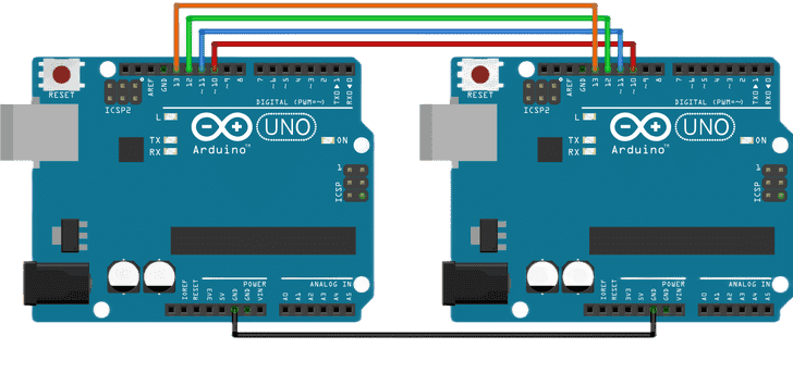
Hardware Setup:

Full Code:
Master Arduino
#include<SPI.h>             //main library


void setup()
{
 Serial.begin(9600);       //MCU & Serial Monitor communication starts
 SPI.begin();              //SPI communication starts

 SPI.setClockDivider(SPI_CLOCK_DIV16);         //data transfering speed
 digitalWrite(SS, LOW);           //the clock pulse started from Master
}


void loop()
{
  SPI.transfer(0xAB);                     //sending 1byte data to Slave
  delay(10);
}
Slave Arduino
#include<SPI.h>                               //main library

int i=0;
volatile bool flag=false;

byte Data;                                    //stores incoming data


void setup()
{
  Serial.begin(9600);
  SPI.setClockDivider(SPI_CLOCK_DIV16);

  pinMode(SS, INPUT_PULLUP);                  //make this device slave
  pinMode(MISO, OUTPUT);                      //transfer data to Master

  SPCR |= _BV(SPE);
  SPCR |= !(_BV(MSTR));

  SPI.attachInterrupt();                      //data handler
}


void loop()
{
  if(flag == true)                         //data received confirmation
  {
    Serial.println(Data);
  }
  flag = false;                            //flag reset for next loop

  delay(10);
}


ISR(SPI_STC_vect)
{
  Data= SPDR;
  flag=true;                               //data received confirmation
}
Code Explanation:
At Master
SPI.begin();SPI.begin() only used for Master, in slave we need to write multiple lines to establish the communication.
SPI.setClockDivider(SPI_CLOCK_DIV16);Setting the data transferring speed at 1Mbit/s. Others option are "SPI.setClockDivider(SPI_CLOCK_DIVa)" where a=2,4,6,8,16,........
digitalWrite(SS, LOW);The clock pulse started from Mastera, Slave cant start clock pulses. Without clock pulses, data can not be transferred.
At Slave:
volatile bool flag=false;By using "volatile" we specified/fixed a memory location for "flag" which is a "bool" type variable, so next time when we need to access this variable compiler will know the exact location, the compiler won't need to reload and recheck variable's current/new memory location, unlike regular "int, float, char, bool" type variable. Learn more about it.
pinMode(MISO, OUTPUT); This line helps to transfer data from Slave to Master. Though we dont need to transfer data from Slave to Master here but I think it's a good practice to use a common pattern everywhere.
SPCR |= _BV(SPE);
SPCR |= !(_BV(MSTR));
These 2 lines help to establish SPI communication from the Slave side, where at the master we only used "SPI.begin()"
SPI.attachInterrupt(); When there will be any interference/data transfer, a default "ISR(SPI_STC_vect)" function will run automatically to send & receive data. Here "SPI_STC_vect" is known as SPI status vector.
Serial.println(Data); "println" only prints Decimal value, so without ( , HEX), we will see 171, always keep eye on ASCII table
Data= SPDR;"SPDR" is the register where data is saved byte by byte, but old data is replaced immediately after new data comes, that's why this function has to be as smallest as possible. No delay/print function can be used here. Because these functions may increase the run time and we can lose data. Here incoming byte from Master will be stored in "Data" variable
Result:
Slave's Serial Monitor

See More Examples:


Comments